- 您现在的位置:买卖IC网 > Sheet目录477 > MICRF009BM TR (Micrel Inc)IC RCVR UHF 300-440MHZ 16-SOIC
�� �
�
�Micrel�
�MICRF009�
�Additional� Applications� Information�
�In� addition� to� the� basic� operation� of� the� MICRF009,� the�
�following� enhancements� can� be� made.� In� particular,� it� is�
�strongly� recommended� that� the� antenna� impedance� is�
�matched� to� the� input� of� the� IC.�
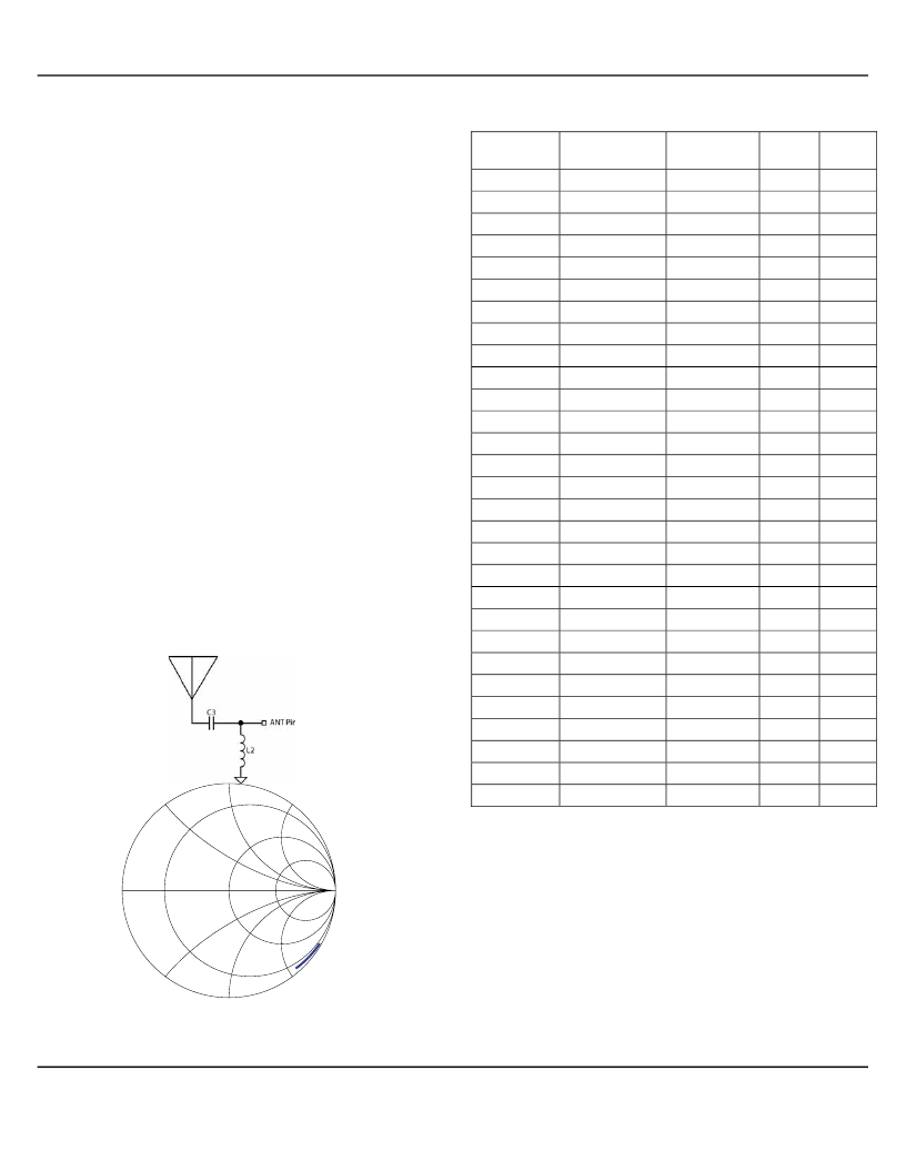
�Antenna� Impedance� Matching�
�As� shown� in� Figure� 7,� and� Table� 4,� the� antenna� pin� input�
�impedance� is� frequency� dependent.�
�The� ANT� pin� can� be� matched� to� 50� ?� with� an� L-type� circuit�
�as� shown� in� Figure� 3.� That� is,� a� shunt� inductor� from� the�
�antenna� input� to� ground� and� another� in� series� from� the�
�antenna� input� to� the� ANT� pin.�
�Inductor� values� may� be� different� from� Table� 4,� depending�
�on� PCB� material,� PCB� thickness,� ground� configuration,� and�
�how� long� the� traces� are� in� the� layout.� Values� shown� were�
�characterized� for� a� 0.031”� thickness,� FR4� board,� solid�
�ground� plane� on� bottom� layer,� and� very� short� traces.�
�MuRata� and� Coilcraft� wire-wound� 0603� or� 0805� surface�
�mount� inductors� were� tested,� however,� any� wire-wound�
�inductor� with� high� SRF� (self-resonance� frequency)� should�
�do� the� job.�
�Shutdown� Function�
�Duty-cycled� operation� of� the� MICRF009� (often� referred� to�
�as� polling)� is� achieved� by� turning� the� MICRF009� on� and� off�
�via� the� SHUT� pin.� The� shutdown� function� is� controlled� by� a�
�logic� state� applied� to� the� SHUT� pin.� When� VSHUT� is� high,�
�the� device� goes� into� low-power� standby� mode.� This� pin� is�
�pulled� high� internally,� and� it� must� be� externally� pulled� low�
�to� enable� the� receiver.�
�Frequency�
�(Mhz)�
�300�
�305�
�310�
�315�
�320�
�325�
�330�
�335�
�340�
�345�
�350�
�355�
�360�
�365�
�370�
�375�
�380�
�385�
�390�
�395�
�400�
�405�
�410�
�415�
�420�
�425�
�430�
�435�
�S11�
�Mag,� angle�
�0.944,-36.65�
�0.940,-37.499�
�0.942,-37.579�
�0.945,� -37.66�
�0.943,-38.237�
�0.942,� -38.814�
�0.94,� -39.39�
�0.938,� -39.967�
�0.937,� -40.544�
�0.935,� -41.12�
�0.933,� -41.697�
�0.931,� -42.274�
�0.93,� 42.85�
�0.928,� -43.427�
�0.926,� -44.004�
�0.925,� -44.581�
�0.923,� -45.157�
�0.921,� -45.734�
�0.92,� -46.311�
�0.917,� -46.729�
�0.914,� -47.148�
�0.912,� -47.566�
�0.909,� -47.985�
�0.907,� -48.403�
�0.906,� -48.797�
�0.909,� -49.152�
�0.911,� -49.507�
�0.911,� -49.925�
�Z11,� ohms�
�14.45-j150�
�14.84-j145�
�14.28-j145�
�13.48-j145�
�13.58-j143�
�13.43-j140�
�13.5-j138�
�13.59-j136�
�13.44-j134�
�13.51-j132�
�13.57-j130�
�13.62-j123�
�13.48-j126�
�13.52-j124�
�13.57-j122�
�13.42-j120�
�13.46-j118�
�13.49-j117�
�13.35-j115�
�13.6-j114�
�13.89-j113�
�14.00-j112�
�14.25-j110�
�14.34-j109�
�14.28-j108�
�13.63-j107�
�13.15-j107�
�12.94-j106�
�C3,� pF�
�2.2�
�2.2�
�2.2�
�2.2�
�2�
�1.8�
�1.8�
�1.8�
�1.8�
�1.8�
�2�
�2.2�
�2.2�
�2�
�1.8�
�2.2�
�2�
�1.8�
�1.8�
�1.8�
�2�
�1.8�
�1.8�
�2.2�
�2�
�2�
�1.8�
�1.8�
�L2,� nH�
�47�
�47�
�47�
�47�
�47�
�47�
�47�
�43�
�43�
�43�
�39�
�36�
�36�
�36�
�36�
�33�
�33�
�33�
�33�
�33�
�30�
�30�
�30�
�27�
�27�
�27�
�27�
�27�
�j25�
�j100�
�440�
�0.904,� -50.571�
�13.66-j104�
�1.8�
�27�
�Table� 4�
�0�
�–j25�
�50�
�Figure� 7�
�–j100�
�∞�
�January� 18,� 2005�
�12�
�M9999-011805�
�(408)� 955-1690�
�发布紧急采购,3分钟左右您将得到回复。
相关PDF资料
MICRF010BMTR
IC RCVR UHF 300-440MHZ 8-SOIC
MICRF011BM TR
IC RCVR/DATAMOD300-440MHZ 14SOIC
MICRF022YM-FS12
IC RECEIVER ASK 300-440MHZ 8SOIC
MICRF211AYQS TR
IC RCVR 3V 433.92MHZ 16-QSOP
MICRF213AYQS TR
IC RX 3.3V 300-350 MHZ 16QSOP
MICRF218AYQS TR
IC RCVR QWIKRADIO 3.3V 16QSOP
MICRF219AAYQS TR
IC RECEIVER QWIKRADIO 16QSOP
MICRF219AYQS TR
IC RECEIVER QWIKRADIO 16QSOP
相关代理商/技术参数
MICRF009YM
功能描述:射频接收器 300-440MHz High Sensitivity Receiver( Lead Free)
RoHS:否 制造商:Skyworks Solutions, Inc. 类型:GPS Receiver 封装 / 箱体:QFN-24 工作频率:4.092 MHz 工作电源电压:3.3 V 封装:Reel
MICRF009YM TR
功能描述:射频接收器 300-440MHz High Sensitivity Receiver( Lead Free)
RoHS:否 制造商:Skyworks Solutions, Inc. 类型:GPS Receiver 封装 / 箱体:QFN-24 工作频率:4.092 MHz 工作电源电压:3.3 V 封装:Reel
MICRF010
制造商:MICREL 制造商全称:Micrel Semiconductor 功能描述:QwikRadio Low-Power UHF Receiver
MICRF010BM
功能描述:IC RCVR UHF 300-440MHZ 8-SOIC RoHS:否 类别:RF/IF 和 RFID >> RF 接收器 系列:- 产品培训模块:Lead (SnPb) Finish for COTS 产品变化通告:Product Discontinuation 09/Jan/2012 标准包装:50 系列:* 频率:850MHz ~ 2.175GHz 灵敏度:- 数据传输率 - 最大:- 调制或协议:- 应用:* 电流 - 接收:* 数据接口:PCB,表面贴装 存储容量:- 天线连接器:PCB,表面贴装 特点:- 电源电压:4.75 V ~ 5.25 V 工作温度:0°C ~ 85°C 封装/外壳:40-WFQFN 裸露焊盘 供应商设备封装:40-TQFN-EP(6x6) 包装:托盘
MICRF010BMTR
功能描述:IC RCVR UHF 300-440MHZ 8-SOIC RoHS:否 类别:RF/IF 和 RFID >> RF 接收器 系列:- 产品培训模块:Lead (SnPb) Finish for COTS 产品变化通告:Product Discontinuation 09/Jan/2012 标准包装:50 系列:* 频率:850MHz ~ 2.175GHz 灵敏度:- 数据传输率 - 最大:- 调制或协议:- 应用:* 电流 - 接收:* 数据接口:PCB,表面贴装 存储容量:- 天线连接器:PCB,表面贴装 特点:- 电源电压:4.75 V ~ 5.25 V 工作温度:0°C ~ 85°C 封装/外壳:40-WFQFN 裸露焊盘 供应商设备封装:40-TQFN-EP(6x6) 包装:托盘
MICRF010YM
功能描述:射频接收器 Low Power 300-440MHz High Sensitivity Receiver( Lead Free)
RoHS:否 制造商:Skyworks Solutions, Inc. 类型:GPS Receiver 封装 / 箱体:QFN-24 工作频率:4.092 MHz 工作电源电压:3.3 V 封装:Reel
MICRF010YM TR
功能描述:射频接收器 Low Power 300-440MHz High Sensitivity Receiver( Lead Free)
RoHS:否 制造商:Skyworks Solutions, Inc. 类型:GPS Receiver 封装 / 箱体:QFN-24 工作频率:4.092 MHz 工作电源电压:3.3 V 封装:Reel
MICRF011
制造商:MICREL 制造商全称:Micrel Semiconductor 功能描述:QwikRadiotm Receiver/Data Demodulator Preliminary Information